Only one sensor required for multiple frequency applications, saving significant cost. Measurements available when frequency is +/-10% of the calibrated frequency.
Measure all parameters available for up to 15 harmonics of the fundamental frequency and plot a harmonic profile.
1% Accurate voltage, current, power and impedance over a range of impedances traceable to NIST, ensuring reproducible and repeatable data from sensor to sensor.
Measure the ion flux to your substrate live on your tool.
Measure the RF waveform live inline at high powers.
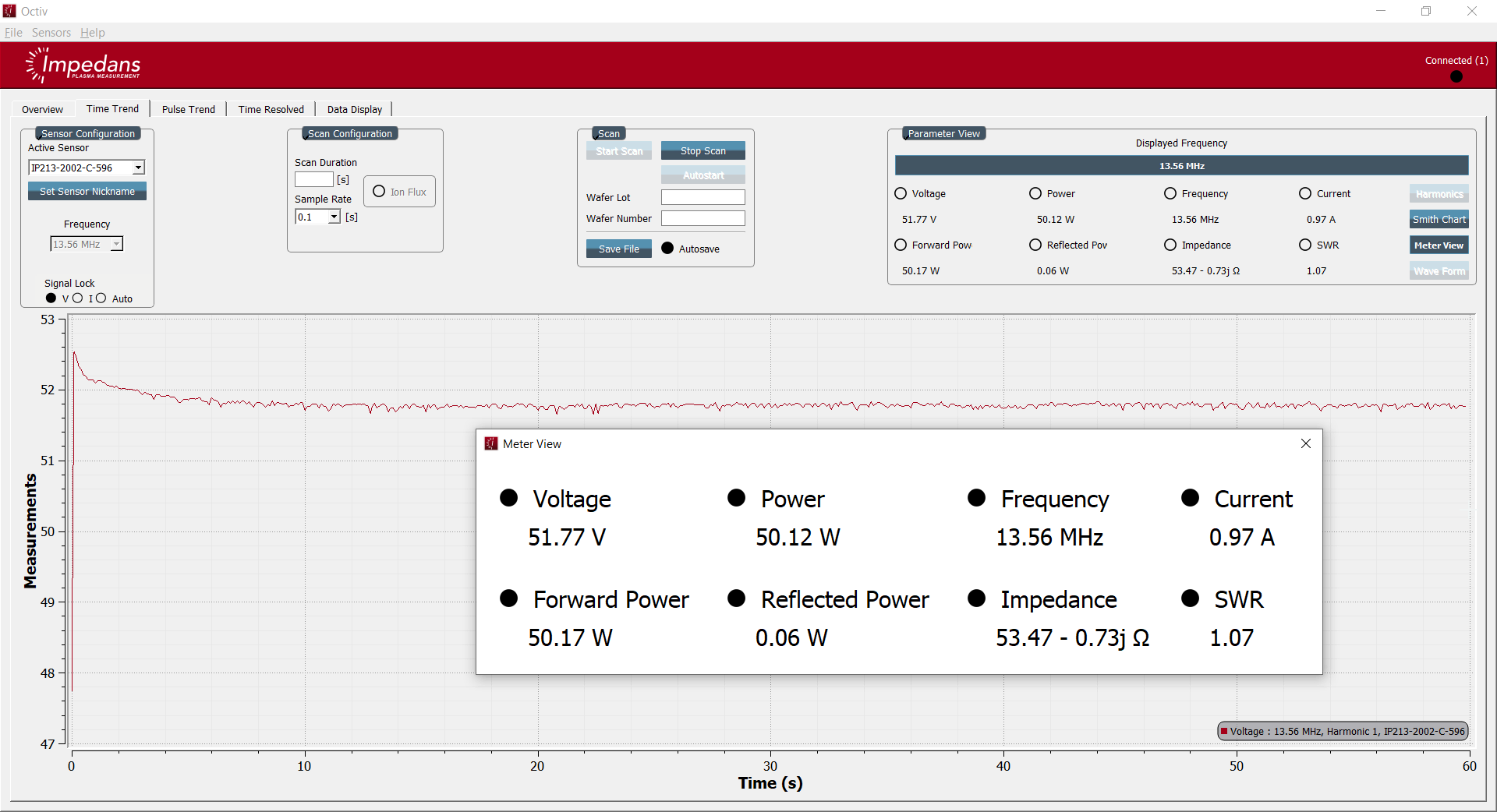
Our software, which can be installed on any PC or laptop, is very intuitive and user friendly.
We have multiple models to suit you installation and voltage/current/power requirements for seamless integration into your process equipment and control loop.
Measure the waveform of your pulse with our time-resolution mode.
Ethernet, EtherCAT, RS232 and USB APIs available for ease of integration with any system.
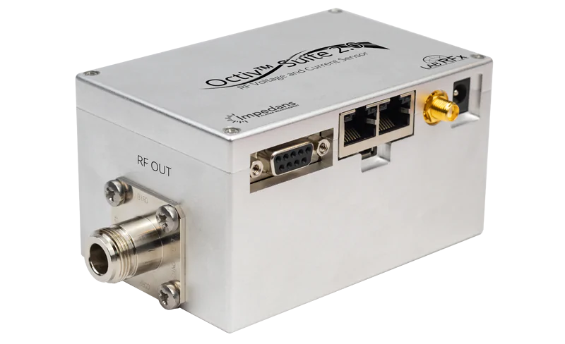
The Octiv Suite 2.0 VI probe is the most advanced RF sensor on the market for in-line power and impedance measurement with unrivalled accuracy and functionality. With 1% true accuracy, chamber-to-chamber matching and process repeatability can be established with confidence. This sensor is designed for advanced R&D and live process monitoring. It combines the pulse monitoring features of the Octiv Mono and the harmonic spectrum capabilities of the Octiv Poly with advanced functionality such as reconstruction of the time domain RF voltage and current waveform, using proprietary harmonic phase deconvolution techniques in the digitization process, making real time monitoring of the ion flux possible when mounted in-line with the process substrate. Uniquely, this sensor
allows the process electrode to be employed in a secondary role as a planar Langmuir probe, enabling plasma density and electron temperature determination.

Five fundamental frequencies on a single sensor, saving cost of purchasing multiple sensors and time having to switch between sensors when taking readings. This also enables measurements of multiple frequencies simultaneously on the same line for multi frequency applications.
RF Frequency tracking band of ± 10% around the fundamental frequency allows accurate readings even when the frequency is variable around the fundamental.

Measure all parameters for up to 15 harmonics of each fundamental frequency and plot a harmonic profile for each frequency (shown on left). The harmonics can detect changes in plasma which can be used to detect faults, end-points and plasma stability.

Achieve in-line accuracy specifications comparable to expensive offline vector network analyzers.
Our calibration uses RF calorimetry and vector network analyzer technology to embed the power of both methods in a compact and responsive form factor. Due to the sampling methods used in our technology we do not require the same amount of averaging as a calorimeter or directional coupler to provide an accurate reading meaning you get quicker accurate readings.
Our sampling methods also use advanced harmonic rejection which ensures accurate power measurement at the selected frequency only and does not require any physical filters.
Our sensors are also calibrated up to 80° C to compensate for temperature variation.
Sensor run-to-run repeatability (< 0.1%), enabling a true gauge of plasma process drift.

The Octiv Suite 2.0 comes with the ability to measure the ion flux to the substrate live. This is very valuable for process monitoring and can detect faults as well as allowing tools to control the ion flux in a closed loop circuit.
The Octiv Suite 2.0 can measure the waveform of the RF live in-line up to high powers essentially giving you an inline oscilloscope. This is very useful when developing processes or equipment as the plasma is controlled by the shape of the RF waveform.
Our software has been designed to be easy to use. It can be installed on any laptop or PC using our simple installers.
Our software can be used to control multiple sensors simultaneously allowing you to monitor multiple locations at once. The software is also compatible across Octiv models meaning multiple Octiv models can be controlled from a single computer.
Once installed the software allows the user to select between sensors, configure each sensor, runs scans, visualize live data and import/export data for analysis.


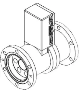
We have multiple models of sensor to allow for varying installation locations and power/voltage/current requirements.
Our standard QC connector model can come with various connectors (see datasheet for full list of connectors) that can be chosen at the time of ordering.
All of our socket style connectors come with a leaf spring design (as shown in the image) which ensures that good electrical contact is made between the pin and the socket.
Auto-switching between CW and Pulsed RF monitoring in time average mode (TAM).
Reports pulse frequency and duty cycle with
sub-microsecond precision in TAM.
Integrates over pulse profile for accurate average
power and impedance measurement.
Time-resolved mode with 1 microsecond resolution
for detailed pulse waveform analysis.
Pulse-trend mode to monitor a number of points within the pulse profile, with 1 microsecond gate times

Software or systems on your site can communicate directly with the sensor without using our software through our API protocols. The sensor is enabled for RS232, USB and Ethernet or EtherCAT.
For more details on the API please contact us.
Quick Change
6mm Socket
20mm Socket
1 5/8 EIA
3 1/8 EIA
| Part Number | Frequency Range | Max Power | Max Voltage/Current | Connectors | |
|---|---|---|---|---|---|
|
02-0325-01 |
40kHz-4MHz |
0.5W – 5KW * |
1.85kVpk/9Arms |
Quick change** |
|
|
02-0322-02 |
350kHz – 240MHz |
1.5W – 12KW * |
1.85kVpk/9Arms |
Quick change** |
|
|
02-0312-01 |
350kHz – 240MHz |
1.5W – 12KW * |
1.85kVpk/80*Arms |
6mm Socket |
|
|
02-0315-01 |
350kHz – 240MHz |
1.5W – 12KW * |
22.6kVpk-pk/120Arms |
20mm Socket |
|
|
02-0319-01 |
350kHz – 240MHz |
3W – 30KW * |
19.8kVpk-pk/120Arms |
EIA 1-5/8″ |
|
|
02-0321-01 |
350kHz – 240MHz |
9W – 90KW * |
33.9kVpk-pk/500Arms |
EIA 3-1/8″ |
*Connector dependent, see our product datasheet for more information
** See our datasheet for a list of available quick change connectors